Locomotive Camera
To see the camera operating on my home layout in a live video feed  click here.
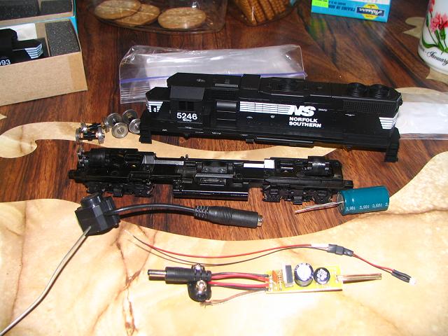
Picture 00
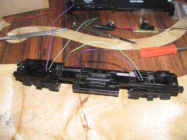
These are the items I started out with. They include, an Athearn dummy
locomotive, replacement wheels (the dummy unit comes with plastic
wheels), capacitor (4700 uF), wireless pinhole camera, and one battery
eliminator circuit.
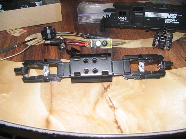
Picture 01
Remove the shell from the frame, and remove the trucks from the frame.
If you want to use the frame as a conductor, file the surface
around the pivot points. I would suggest not doing this, as I prefer
to solder the wire directly to the trucks.
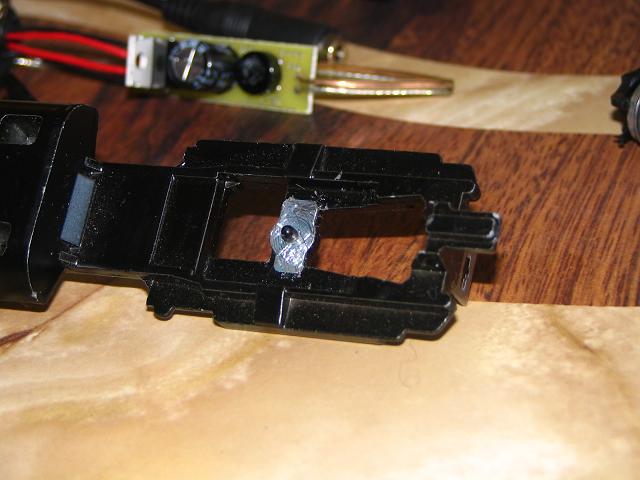
Picture 02
Here is a closer view of the pivot point on the Athearn frame.
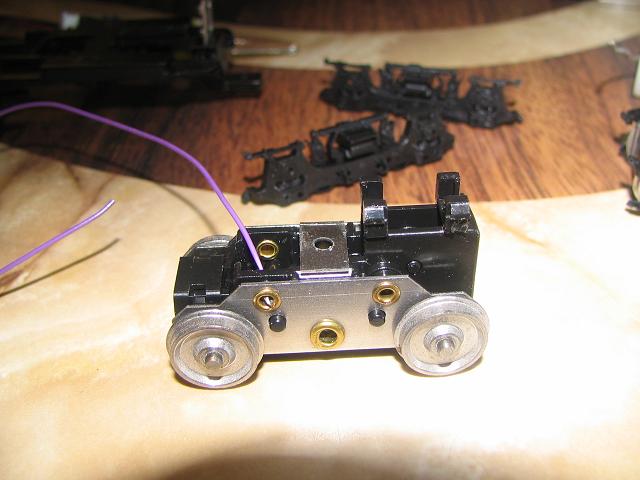
Picture 03
Take some wire and feed it into the brass rivet holes from the inside of the truck. Solder
them in place. Take another wire and feed it into the other
rivet holes for the opposite side wheels. Repeat this process for both front and rear trucks.
Picture 04
Attach the trucks back to the frame of the locomotive. Make sure
that the wires come through the opening of the frame well.
Picture 05
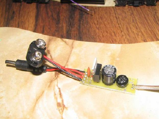
Take the battery eliminator circuit provided my wirelessmicrocolorcam.com and remove the nine volt batter clip. I just twisted it until it broke off.
Picture 06
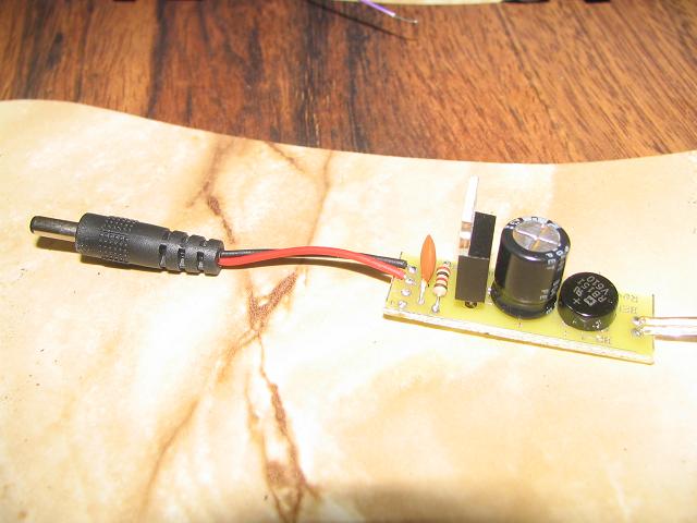
It now looks like this.
Picture 07
Take the cab off the shell of the locomotive.
Picture 08
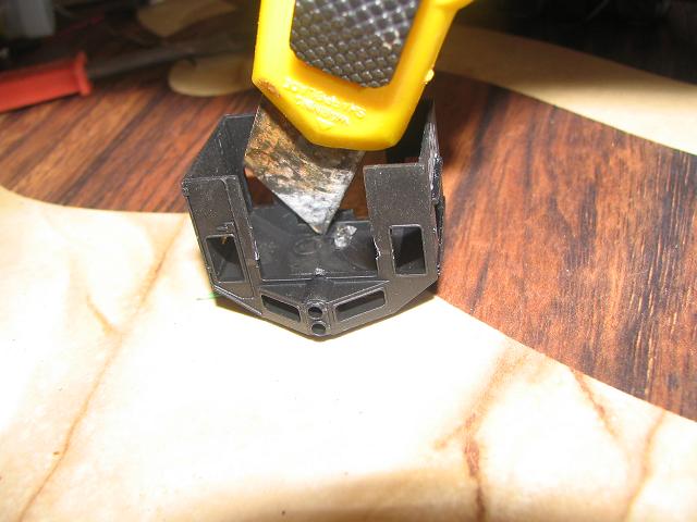
As close to the back edge as possible cut through the hood of the cab.
Once through, turn it over and cut a square the shape of the pin hole
camera.
Picture 09
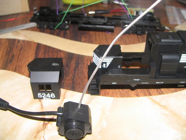
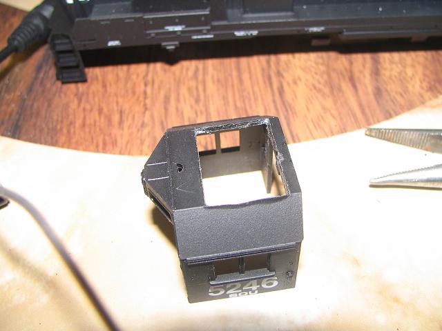
Here is my finished hole. Test fit the camera, so that the top of the camera is flush with the top of the cab.
Picture 10
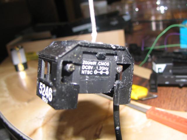
Here is the back of the locomotive cab with the Camera installed. I
chopped the plastic from the sides of the windows to make room for the
screw tops of the camera, Its a tight fit. Don't forget to try the
camera out, adjusting the focus before gluing it in place. You can
adjust it later, but its more difficult.
Picture 11
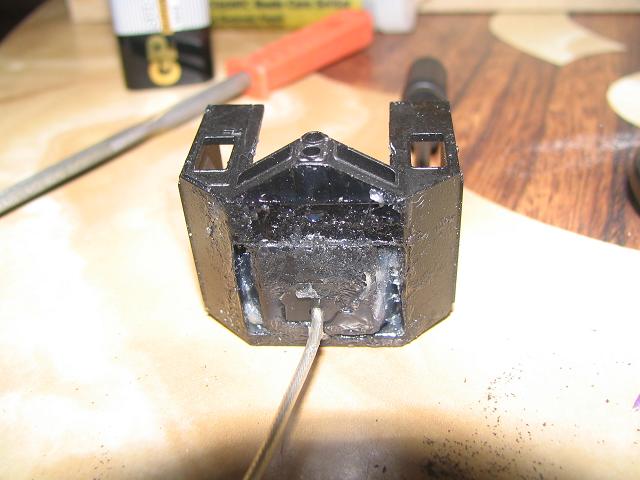
I used five minute epoxy to glue the camera into the cab of the
locomotive. It filled in the gaps nicely. THe epoxy can be filed down
later to painting.
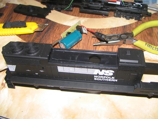
Picture 12
Remove the dynamic braking hatch. Athearn dummy shells have
additional plastic for holding a counter weight. Remove
this plastic.
Picture 13
This is the shell after removing the extra plastic. The added room makes for the battery eliminator circuit.
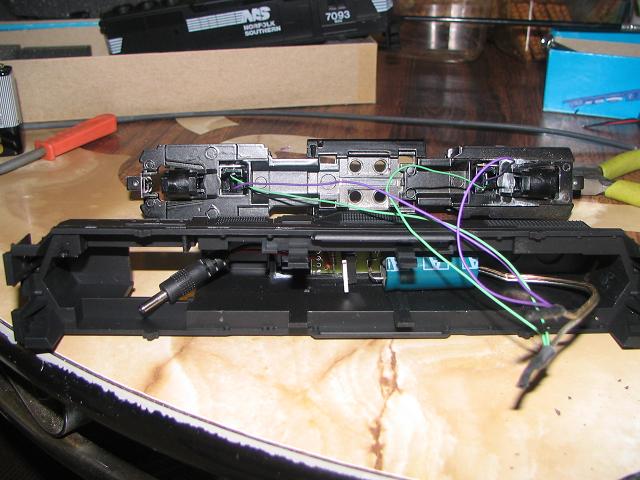
Picture 14
Attach the wires from the trucks/frame of the locomotive to the battery
eliminator circuit. Make sure the circuit board fits into the shell
well.
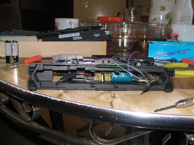
Picture 15
Another picture.
Picture 16
The epoxy should be dry by now. Careful place the cab back onto the shell.
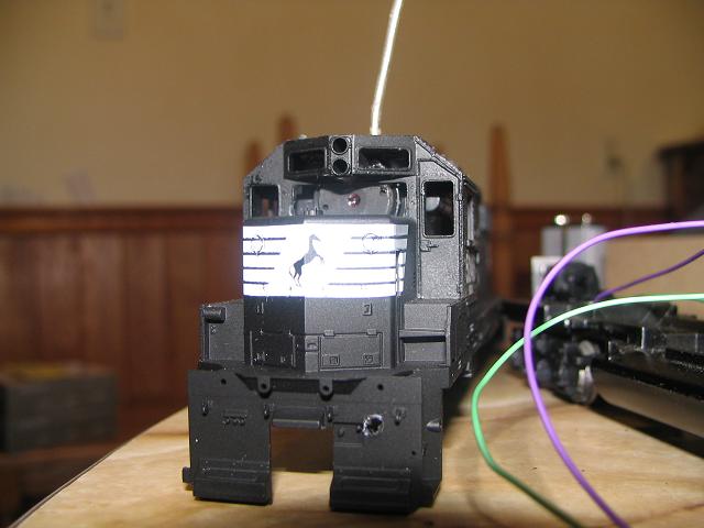
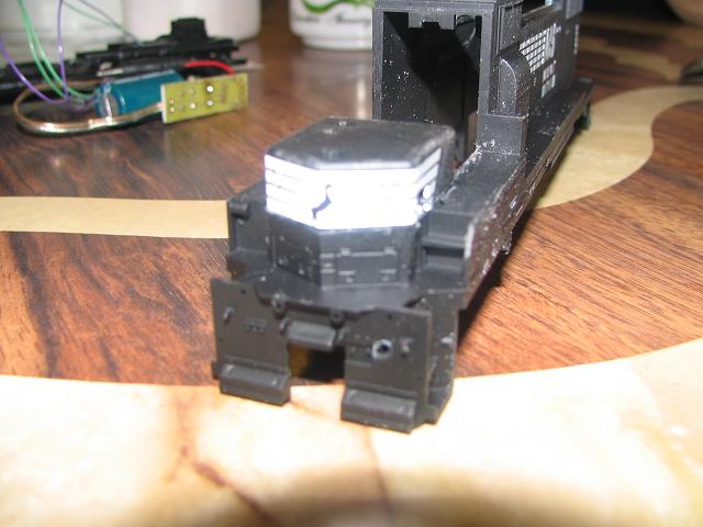
Picture 17
Here is another view of the hidden camera in the cab of the locomotive.
The camera is black, which hides well with the black paint scheme of
Norfolk Southern.
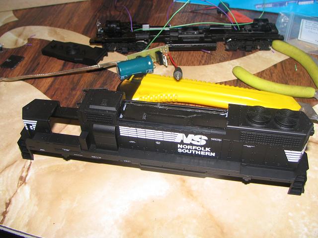
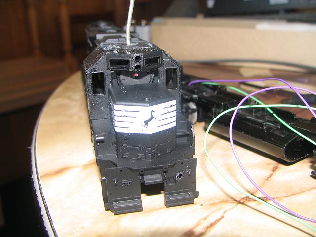
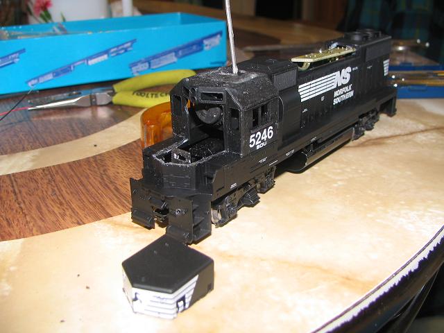
Picture 18
Here is a picture of the locomotive with the shall back on the frame.
Test the view of the camera. You might see the nose of the locomotive in
the picture. If this is the case, you will have to lower the nose
of the cab. In my case, the camera shows the nose, but its really fuzzy
being out of focus.
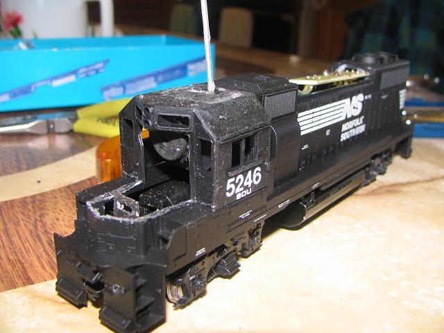
Picture 19
I cut the nose off (ouch that hurt).
Picture 20
File the cut flat so the two pieces can be glued together seamlessly.
Picture 21
If you look carefully, I filed about 1/16 of an inch off (the width of one white stripe of the paint scheme).
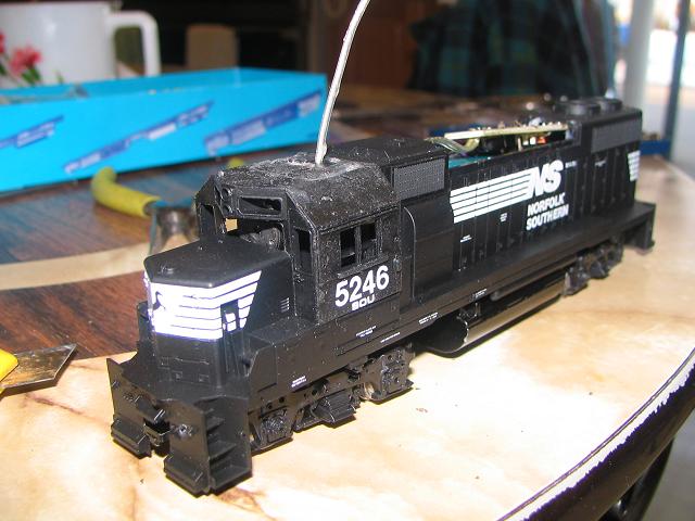
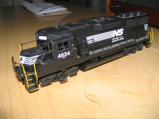
Picture 22
Opps, I forgot to take a picture of the locomotive finished. Oh well,
picture 18 is close enough. I have another picture of a GP50...
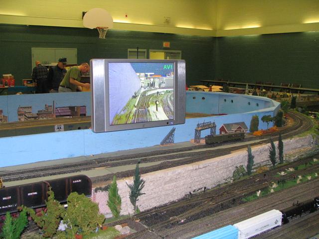
Picture 23
Our train club uses a twenty inch television mounted to display the video from the train camera.